A home network for public facing apps
In my last home server post, I discussed setting up a home server machine which featured a KVM/QEMU hypervisor and LVM for disk management. In this post I will describe a setup to host services publicly. Hosting services publicly should not be treated lightly given it requires opening the “network” door to your home allowing untrusted parties to enter. This post will outline networking segmentation, hardening techniques and network analysis tools that will increase your awareness and reduce the attack surface and blast radius in the event of an attack.
Background
I will begin with network segmentation which includes VLANs and IP subnets. It is apparent a publically facing service if comprimised should not have acces to the rest of the devices in the home network. I will demonstrate how to create VLANs on both physical managed switch and on a virtualized Linux bridge on a server. Here I will also discuss creating a special subnet referred to a Demilitry Zone (DMZ) and creating a reverse proxy to act as a bodyguard for the internal services. There after I will briefly demonstrate selective routing for services which should be exposed to the outside world via a VPN in cases where our home IP address must remian hidden. Finally, since so many services are deployed as Docker containers, I will demonstrate Docker hardening techniques and running containers with unprivileged user ids.
VLANs
To discuss VLANs one must return the OSI model which I discussed in a previous blog post. The simplest network for multiple machines to communicate is at Layer 2 transferring Ethernet between each other via a network switch. In this simple network all devices can communicate with each other. To create another LAN network one could introduce a second switch device and connect different devices to it. Virtual LAN (VLAN), defined in the 802.1Q standard provides a method for creating multiple LAN networks without the need of introducing more switch devices. In the 802.1Q standard, an Ethernet frame has 4 bytes dedicated to a VLAN tag. Only devices participating on the network with the same VLAN tag can communicate with each other. If two devices with two different VLAN tags want to communicate with each other, then they will need to communicate via the internet network protocol (IP) using a Layer 3 device (i.e. a router). Segmenting networks at Layer 2 with VLANs and not trying to segment at Layer 3 makes network management easier to organize since IP address subnet ranges can be given to each VLAN segment and thereafter the L3 firewall rules can target IP subnet ranges as opposed to individual IP addresses. VLAN segmentation also has the additional benefit of reducing broadcast traffic since devices on one VLAN do not respond to ARP requests on another VLAN.
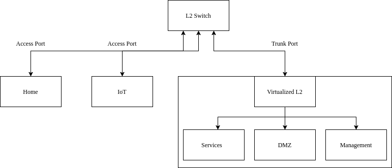
Creating VLANs on a managed switch or virtualized bridge is simple and simply requires you to keep track how you want frames to look going out of the switch (egress) or coming into the switch (ingress). Pay careful attention as “ingress” and “egress” depends on the point view of the either the device or the switch. We define VLANs on the individual ports on the switch or bridge and there are only two types of port configurations, namely: Access ports and Trunk ports. Access ports configured on the switch have untagged traffic coming in from and flowing out to the device. Frames from the device entering the switch are then tagged by the switch and hence the switch is able to determine which L2 network this device belongs on. Trunk ports on the other hand are ports which expect already tagged Ethernet frames arriving upstream and so the switch will process them accordingly.
Mikrotik VLAN configuration
Here I outline the VLAN setup specifically for Mikrotik hardware but I believe conceptually all switches behave similar.
- Access points, you can specify the VLAN ID on the bridge port itself
- For trunk ports
- Typically we want a DHCP server running on each of the VLAN networks
- After DHCP server setup, you must tag the bridge interface itself so it is a part of the VLAN network
- Finally enable VLAN filtering on the bridge
VLANs with iproute2
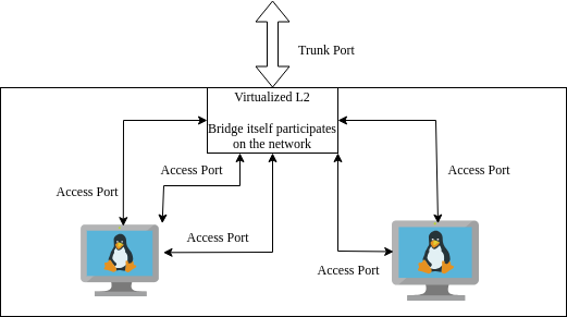
Now consider a virtualized network. On my server I want to separate VMs and applications into their own separate VLANs. To do this without buying additional hardware I will virtualize the switch (now referred to as a bridge) as well as virtualizing the links between the VMs (analgous to the physical Ethernet links connected to devices). Network virtualization is done with iproute2 which is a reference userspace tool for interacting with Linux’s networking subsystem API - netlink. Using this tool, I will create a VLAN aware virtual network for my home server. I believe, a clean stratgey is to have the hypervisor manage all the networking VLAN tagging and not the VM guests themselves. Each guest VM will have a link for each VLAN - since they are virtualized I can add as many as I want - one for each VLAN network. Each link on the guest VM can then be simply configured as an access port on the hypervisor’s bridge. As before each VLAN has an associated static IP address subnet for inter-vlan routing.
Given RouterOS, operating system for Mikrotiks, is Linux based, this adventure will offer greater insight into RouterOS internals. Such information will allow us to turn any Linux machine into a router/firewall.
Kernel build options
In order to set up VLAN aware virtual networking, enable the following kernel config options. They can either be “built in” or built as modules.
CONFIG_VLAN_8021Q=y
BRIDGE_VLAN_FILTERING=y
VLAN interfaces
With the kernel built and rebooted with the correct configuration we can begin setting up the VLAN aware bridge on the hypervisor. The script below highlights this setup. In order it:
- Sets the physical interface link as a trunk port
- Instantiates a VLAN aware bridge
- Adds the physical interface to the bridge
- Adds the VLAN tags which will be transferred over the bridge
- The bridge tags itself so it can participate on the management network with its own VLAN and subnet. Thereafter a rule is created to transmit all tagged frames over a subinterface
- Starts the bridge
- Create virtual tap interfaces representing Ethernet links carrying only a single VLAN tag
- Assign the VLAN tag for those interfaces as access ports. This means traffic from the bridge to guest VM is untagged. Trffic is only tagged by the bridge when passing through the bridge to another destination.
- Finally add those links to the bridge interface and activate the links
The second half of the script describes how to bring down and clean up the current setup.
#!/bin/bash

IF0="ens1"

if [[ $1 = "start" ]]; then

	# ##########################################
	# Set trunk link up
	# ##########################################
	ip link set $IF0 up

	# ##########################################
	# Set up bridge and bridge filtering
	# ##########################################
	ip link add br_hypervisor type bridge vlan_filtering 1 vlan_default_pvid 0

	# ##########################################
	# Attach physical ethernet port to bridge
	# and set as trunck
	# ##########################################
	ip link set $IF0 master br_hypervisor

	# ##########################################
	# Cofigure trunk interface
	# ##########################################
	bridge vlan add dev $IF0 vid 20
	bridge vlan add dev $IF0 vid 30
	bridge vlan add dev $IF0 vid 10

	# ##########################################
	# Host network setup
	# ##########################################
	bridge vlan add dev br_hypervisor vid 10 self
	ip link add link br_hypervisor name br_hypervisor.10 type vlan id 10
	ip link set br_hypervisor.10 up
	ip addr add 192.168.10.2/24 dev br_hypervisor.10

	# ##########################################
	# Bring up bridge interface
	# ##########################################
	ip link set br_hypervisor up

	# ##########################################
	# Create macvtap interfaces
	# ##########################################
	ip tuntap add tp_guest1_mgmt mode tap
	ip link set tp_guest1_mgmt master br_hypervisor

	ip tuntap add tp_guest1 mode tap
	ip link set tp_guest1 master br_hypervisor

	ip tuntap add tp_guest2_mgmt mode tap
	ip link set tp_guest2_mgmt master br_hypervisor

	ip tuntap add tp_guest2 mode tap
	ip link set tp_guest2 master br_hypervisor

	ip tuntap add tp_guest2_dmz mode tap
	ip link set tp_guest2_dmz master br_hypervisor

	# ##########################################
	# Bridge filtering: Assign VLAN access ports
	# ##########################################
	bridge vlan add dev tp_guest1_mgmt vid 10 pvid untagged master
	bridge vlan add dev tp_guest1 vid 20 pvid untagged master

	bridge vlan add dev tp_guest2_mgmt vid 10 pvid untagged master
	bridge vlan add dev tp_guest2 vid 20 pvid untagged master
	bridge vlan add dev tp_guest2_dmz vid 30 pvid untagged master

	# ##########################################
	# Set links up
	# ##########################################
	ip link set tp_guest1_mgmt up
	ip link set tp_guest1 up

	ip link set tp_guest2_mgmt up
	ip link set tp_guest2 up
	ip link set tp_guest2_dmz up

	# ##########################################
	# for some reason, flush fdb table
	# ##########################################
	bridge fdb flush dev br_hypervisor

	# ##########################################
	# Set default route of hypervisor
	# ##########################################
	ip route add default via 192.168.10.1

	# ##########################################
	# Replay VLAN bring up
	# ##########################################
	bridge vlan del dev br_hypervisor vid 10 self
	bridge vlan add dev br_hypervisor vid 10 self

elif [[ $1 = "stop" ]]; then

	# ##########################################
	# Set links down
	# ##########################################
	ip link set tp_guest1_mgmt down
	ip link set tp_guest1 down

	ip link set tp_guest2_mgmt down
	ip link set tp_guest2 down
	ip link set tp_guest2_dmz down

	# ##########################################
	# Delete links
	# ##########################################
	ip link del tp_guest1_mgmt
	ip link del tp_guest1

	ip link del tp_guest2_mgmt
	ip link del tp_guest2
	ip link del tp_guest2_dmz

	ip link del br_hypervisor.10
	ip link del br_hypervisor type bridge

else
	echo "Error! Please pass either 'start' or 'stop' to script"
fi
Inspect VLAN traffic with tcpdump
tcpdump is a useful tool for inspecting network traffic.
tcpdump -i eth0 -nn -e vlanCreating a virtualized DMZ
DMZ stands for demilitarized zone and is simply a subnet like any other on the network which s IP forwarding rules . In this case, the subnet is has rules specifically to access only the internal services.
Inter-vlan routing
As previously mentioned, VLANs segment the network at Layer 2. This means if one device from one VLAN network wants to communicate to another VLAN network we will need to use the inter-network [internet] protocol (IP) at Layer 3. Thus all our devices on all the VLAN networks will require IP addresses. As a quick reminder, the internet protocol works since devices trying to communicate with IP addresses outside the (V)LAN network is forwarded to the routing device which has a routing table to decide where the packet is forwarded to.
In this setup one IP subnet (range of IP addresses) is assigned to a VLAN for all devices local to that VLAN. To make our lives easier, we can instantiate a DHCP server for each VLAN to assign the IP addresses automatically. Alternatively, we can assign static IP addresses to our devices manually.
Finally, to complete the inter-VLAN routing setup, we must specify the gateway address on the VLAN interface of the router. This is so the router device knows to listen for requests destined for the gateway address and thus is able to handle them accordingly using its routing table. The following is an example Mikrotik command to achieve this and must be done for all our VLAN networks.
/ip address add address=192.168.20.1/24 interface=vlan_Services network=192.168.20.0All that is left is to add Layer 3 firewall rules to make this setup secure. The next section will describe this in detail.
General Firewall Rules
Building a Linux firewall requires understanding about the various chains to which you can add and remove rules to. When a network packet passes through the L3 firewall it passes through one or more of these chains. The trick therefore is to think about how the packet is traversing the firewall and hence identify which chain you want to apply the rule to.
There are 3 primary and the 2 optional:
Input (IP packets whose destination is the host [i.e. router])
Output (IP packets whose origin is the host [i.e. router])
Forward (IP packets whose destination needs to be forwarded to another subnet)
Prerouting
Postrouting
Goal is to build a restrictive firewall which means by default traffic is disallowed and we make exceptions for the traffic we do want to allow. Below is a common firewall strategy.
Input chain
- Allow only established connections in on internet interface (INPUT)
- Block everything else on the incoming chain of the internet interface (INPUT)
- Block all other connections incoming on internet interface (INPUT)
Forward chain
- Allow VPN connections to be forwarded to LAN
- Allow fowarding traffic from the different subnets to internet interface (i.e. allow internet access) (FORWARD)
- Allow forwarding traffic from different subnets to services subnet (i.e. allow everyone to access devices on services subnet)
- Allow forwarding traffic from LAN subnet to all other subnets
- Block IoT devices from accessing any other subnet
- Block all other traffic being forwarded to any other device
NAT
- NAT all outgoing connections since our internal network is IPV4
Subnet firewall rules in detail
/ip firewall filter
add action=accept chain=input comment="accept extablished,related,untracked" connection-state=established,related,untracked
add action=drop chain=forward comment=back-to-home-vpn disabled=yes out-interface-list=LAN src-address-list=back-to-home-lan-restricted-peers
add action=accept chain=input comment=back-to-home-vpn dst-port=13233 protocol=udp
add action=drop chain=input comment="drop invalid incoming from WAN" connection-state=invalid in-interface=pppoe-out1
add action=drop chain=input comment="drop everything else incoming from WAN" in-interface=pppoe-out1


add action=accept chain=forward comment="accept established,related" connection-state=established,related
add action=drop chain=forward comment="Drop invalid on forward chain" connection-state=invalid
add action=accept chain=forward comment="Only allow Cloudflare IP address from WAN" dst-address-list=DMZ_REV_PROXY dst-port=443 in-interface=pppoe-out1 protocol=tcp src-address-list=CLOUDFLARE
add action=drop chain=forward comment="Drop everything else on forward chain from WAN" in-interface=pppoe-out1

add action=accept chain=forward comment="Allow DNS server to make requests " out-interface=pppoe-out1 protocol=tcp src-address=<dns_ip>
add action=accept chain=forward dst-port=53,853,443 out-interface=pppoe-out1 protocol=udp src-address=<dns_ip>


add action=accept chain=forward comment="Allow LAN to internet (restricted)" out-interface=pppoe-out1 protocol=tcp src-address-list=LAN_RANGE dst-port=80,443,25,587,993
add action=accept chain=forward comment="Allow LAN to connect to Discord UDP connections" out-interface=pppoe-out1 protocol=udp src-address-list=LAN_RANGE dst-port=50000-65535
add action=accept chain=forward comment="Allow ICMP from LAN" out-interface=pppoe-out1 protocol=icmp src-address-list=LAN_RANGE

add action=accept chain=forward comment="Allow IOT to DNS" dst-address-list=DNS_SERVER src-address-list=IOT_RANGE
add action=accept chain=forward comment="Allow IoT to internet" out-interface=pppoe-out1 src-address-list=IOT_RANGE
add action=drop chain=forward comment="Drop  IoT everywhere else" src-address-list=IOT_RANGE


add action=accept chain=forward comment="Allow Internal Services to DNS" dst-address-list=DNS_SERVER src-address-list=INTERNAL_SERVICES_RANGE
add action=accept chain=forward comment="Allow Internal Services to internet" connection-state=new log=yes out-interface=pppoe-out1 src-address-list=INTERNAL_SERVICES_RANGE
add action=accept chain=forward comment="Allow Internal Services to internet via VPN" connection-state=new log=yes out-interface=wg_ivpn src-address-list=INTERNAL_SERVICES_RANGE
add action=drop chain=forward comment="Drop internal services everywhere else" src-address-list=INTERNAL_SERVICES_RANGE


add action=accept chain=forward comment="Allow DMZ to specific internal services" dst-address-list=DMZ_ALLOWED_SERVICES protocol=tcp src-address-list=DMZ_RANGE
add action=drop chain=forward comment="Block DMZ everywhere else" src-address-list=DMZ_RANGE
add action=drop chain=forward comment="Drop LAN devices from accessing to DMZ directly" dst-address-list=DMZ_RANGE src-address-list=LAN_RANGE
add action=drop chain=forward comment="Drop VPN devices from accessing DMZ directly" dst-address-list=DMZ_RANGE src-address-list=VPN_INTERNAL


add action=accept chain=forward comment="Allow VPN devices to access Internal Services" dst-address-list=INTERNAL_SERVICES_RANGE in-interface=wg_home src-address-list=VPN_INTERNAL
add action=accept chain=forward comment="Allow VPN devices to access Management" dst-address-list=MGMT_RANGE in-interface=wg_home src-address-list=VPN_INTERNAL
add action=accept chain=forward comment="Allow VPN devices to internet" out-interface=pppoe-out1 src-address-list=VPN_INTERNAL
add action=accept chain=forward comment="Allow Management to DNS" dst-address-list=DNS_SERVER src-address-list=MGMT_RANGE
add action=accept chain=forward comment="Allow MGMT to internet" out-interface=pppoe-out1 src-address-list=MGMT_RANGE
add action=reject chain=forward comment="Drop all other connections forwarded to WAN" out-interface=pppoe-out1 reject-with=icmp-network-unreachable
Additional notes about DMZ
/ip firewall add action=drop chain=forward comment="Drop LAN devices from accessing to DMZ directly" dst-address-list=DMZ_RANGE src-address-list=LAN_RANGEPolicy routing
To motivate policy routing I will describe a situation I needed for it. It was important to me that the traffic from some of my devices on my local network go via a VPN. This can be achieved using policy routing which is simply creating a separate routing table, its corresponding default route rule to route via VPN interface and then marking traffic originating from your desired addresses to pass through this new routing table. Thereafter since the devices are participating on an IPV4 network, an additional NAT rules is required to exit via the VPN interface. The commands to achieve this on a Mikrotik are as follows assuming a VPN interface is already setup.
/routing table add disabled=no fib name=tbl_vpn

/ip route add check-gateway=none disabled=no distance=1 dst-address=0.0.0.0/0 gateway=wg_ivpn routing-table=tbl_vpn scope=30 suppress-hw-offload=no target-scope=10

/ip firewall mangle
add action=mark-routing chain=prerouting dst-address-list=!RFC1918_Networks new-routing-mark=tbl_vpn src-address-list=VPN_EXTERNAL
add action=mark-connection chain=prerouting dst-address-list=!RFC1918_Networks new-connection-mark=tbl_ivpn src-address-list=VPN_EXTERNAL
add action=change-mss chain=forward connection-mark=tbl_ivpn new-mss=clamp-to-pmtu out-interface=wg_ivpn protocol=tcp tcp-flags=syn

/ip firewall nat add action=masquerade chain=srcnat comment="Masquerade addresses out of VPN" out-interface=wg_ivpn src-address-list=VPN_EXTERNAL
The following link includes a detailed tutorial:
https://rfranzen.com/post/2023-04-ivpn-mikrotik/
For another usecase of policy routing refer to the Docker section at the end.
Proxies
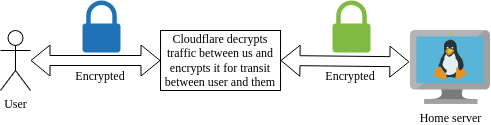
Cloudflare
Cloudflare as a DNS provider offers to freely proxy all requests destined for your public facing applications. By proxying your requests, Cloudflare will be able to detect attacks (commonly DDOS attacks) and block them before reaching your application. Of course this comes with an element of trust as their hardware will decrypt traffic between you and cloudflare and then encrypt it using their own certificates between the client and them. However, as a company specialising in internet security I believe this is a minor issue and their is still opportunity to improve security further on the networks we control. It is vital to understand Cloudflare reverse proxy is not silver bullet to internet security. A vunerablility in your public facing application that can be exploited through a valid request will not be blocked by Cloudflare and can still comprimise your entire system.
NGINX Reverse Proxy
With the router upgrade, I decided to swap out my NGINX proxy manager container instance and instead spin up a dedicated VM running normal NGINX. Learning NGINX opens the opportunity to have greater control on the behaviour of the reverse proxy.
Nginx is a powerful open source web server. A web server simply “serves” static files found on the computers filesystem over an HTTP connection. Simply a client makes a request for a file using an HTTP request, Nginx will listen to the request and serve the requested file back to the user over HTTP. This flow also highlights Nginx’s ability to act as a reverse proxy. A reverse proxy is essentially web server which sits between your internal services (e.g. other web servers) and the client. The are many benefits to having a middleman between the client and internal service. Examples include:
- consolidating all connection policies for all your internal services in a single location
- A single point for SSL termination. Use one certificate for different internal services
- Act as the body guard between the client and internal services applying policies such as geoblocking and rate limiting
The general structure of a Nginx configuration is to define server blocks. As a reverse proxy, it is up to Nginx to receive a request and determine which server block must handle the request which it will do based on server name. Then Nginx will look at the location defined in the server block. A single server can have multiple locations and corresponding policies on how to handle those locations. As a reverse proxy, Nginx will determine the location and using the proxy_pass parameter will forward the request. Additonally, Nginx will allow us to mold the request further by setting HTTP header values when passing to internal service instance. The server configuration located in /etc/nginx/conf.d/default.conf.
# Global server to reroute all HTTP to HTTPS
server {
    listen 80;
    server_name _; # Catch all server name for all requests

    return 301 https://$host$request_uri; # Redirect everything to HTTPS
}

# Internal service 1
server {

    listen 443 ssl http2;
    server_name api.myservice.com;

    ssl_certificate     /etc/ssl/myservice.com/cloudflare_origin_cert.pem;
    ssl_certificate_key /etc/ssl/myservice.com/cloudflare_origin_key.pem;

    location / {
        proxy_pass http://192.168.20.5:44311;   # Backend service URL (and IP)
        proxy_set_header Host $host;
        proxy_set_header X-Real-IP $remote_addr;
        proxy_set_header X-Forwarded-For $proxy_add_x_forwarded_for;
        proxy_set_header X-Forwarded-Proto $scheme;
    }

}
Hardening NGINX
Although setting up the reverse proxy is the first step in securing your services, there are a number of tweaks available to us to “harden” our reverse proxy.
Nginx operates at Layer 7 specifically the HTTP application requests (synomous with web page requests). Thus in order to harden or tune Nginx to ensure security one must be familiar with the HTTP protocol. As quick refresher, the HTTP protocol sits at the last layer of the OSI model. After two computers can communicate over different networks (internet), have agreed on how packets are transported (TCP/UDP) over an established session and agreed on what the actual bits being transfer actually means (e.g. what the encoding is and whether they are encrypted or not); only then must the two computers decide on how to structure those bits for the purposes of transferring web pages.
I think HTTP is so prevalent due to its flexibility. In order to be flexible every HTTP request includes a lot of metadata in the form of headers. Header information allows the client to request data from the server in a way unique to itself. For instance a mobile device requires very different data from the server than a desktop for example. There are many headers defined in the HTTP standard and are documented here. As we will see, much of a reverse proxy’s concerns sit with what headers are allowed or forced.
- Enforce TLS version 3.1 and greater
server {

   ssl_protocols TLSv1.3;

}- Rate limit authentication URLs
limit_req_zone $binary_remote_addr zone=api_limit:10m rate=10r/s;

sever {
#...
            limit_req zone=api_limit burst=20 nodelay;
            limit_req_status 429;
            proxy_pass http://backend;
#...
}- Whitelisting trusted IP addresses
sever {
#...
            allow 192.168.1.10;
            allow 203.0.113.0/24;
            deny all;

#...
}- Headers and content policies
server {

#...

    add_header X-Content-Type-Options "nosniff" always;
    add_header X-Frame-Options SAMEORIGIN;
    add_header X-XSS-Protection "1; mode=block";
    add_header Strict-Transport-Security "max-age=31536000" always;
    add_header Referrer-Policy "strict-origin-when-cross-origin";
    add_header Content-Security-Policy "
	default-src 'self';
	script-src 'self' 'unsafe-inline';
	script-src-attr 'self' 'unsafe-inline';
  	style-src 'self' 'unsafe-inline';
  	img-src 'self' data: https://api.myservice.com;
  	font-src 'self' https://fonts.gstatic.com;
  	connect-src 'self' https://api.myservice.com  https://cdnjs.cloudflare.com;
  	media-src 'self' blob:;
  	object-src 'self' blob;
	frame-src 'self' blob;
	navigate-to 'self' blob;
  	worker-src 'self' blob:;
  	base-uri 'self';
  	frame-ancestors 'none';
  " always;

  #...

}
Ready for the public
CGNAT vs public IP address
I have explored NAT in a previous post before but as a quick summary: NAT is a technique to reuse IP addresses in IPV4 networks since the number of devices which participate on the public internet has exceeded the number of available IP addresses IPV4 can provide. This works as a home or business may be assigned a single public IP address and all the devices behind the router are assigned private IP addresses. These private IP addresses are the addresses that are reused between companies and businesses elevating the burden of each of these devices getting a IP address from the short supply of public addresses. These private IP addresses can still participate on the public network because before their packets are sent out the router will substitute the private address for its own address and keep track so it knows where relies should go to. This is NAT briefly. Note private does not mean secure - it is simply reuse.
When it comes to home networks ISPs may take this NAT one step further. Your ISP may have provided you not a public IP address but one from there own internal network which is then NAT-ed using their public IP address. Essentially this means your home devices are NAT-ed from your private IP space to the private space of the ISP and then again to the public IP address of the ISP. This double NAT (or CGNAT) means clients from the public internet can’t initiate requests with you since they can’t know what private IP address your ISP has assigned to you and whether or not they change it later. Thus in order to make any services publically available you must request a public IP address from your ISP posssibly for an extra fee.
Dynamic DNS (DDNS)
Given you might have a public IP address, your ISP may still decide to change it arbitarly depending on their needs. Thus is also necessary in a home network environment to have a dynamic DNS service. Mikrotik has a useful DDNS service builtin into their routers branded as /ip/cloud. Mikrotik assigns your public IP address to one of their generated URLS. With this URL you can create a CNAME entry with your hosting provider, hence your desired domain name maps to your public IP address via Mikrotik’s domain automatically. If you don’t have a Mikrotik you can use a provider like DuckDNS.
Port forwarding (Destination NATing)
Finally, it is time to allow incoming requests from the outside world to reach our public facing applications. In my case, as with best practices, the only port open points to the reverse proxy which will redirect to the requested service.
Also since I am using Cloudflare’s proxy service as mentioned earlier, I know I only want to accept requests from Cloudflare’s IP address range.
/ip firewall nat add action=dst-nat chain=dstnat comment="Allow connections from WAN to DMZ" dst-port=443 in-interface=pppoe-out1 protocol=tcp src-address-list=CLOUDFLARE to-addresses=<rev_proxy_ip>syslog server
Logs crucially allow you to stay aware with what is happening with your VMs and networking. We can set up a syslog server to have a single place where all logs are stored for VMs, applications and networking.
- Create separate system logs partition
- Mount partiton
- Configure
- logrotate
systemd-journald captures:
- kernel logs (includes the creation of ip links, bridges etc.)
- services information
Additional services which need to be sent to syslog:
- netconsole (when systemd fails us), specifically will help capture watchdog logs for soft lockups
edit /etc/default/netconsole.conf (configure remote server here) edit /etc/sysctl.d/99-kernel-watchdog.conf (enable watchdog and parameters here)
- docker containers
edit /etc/docker/daemon.conf
- snort3 intrusion detection system
- fail2ban
Intrusion Detection System (IDS)
Snort is a Intrusion Detection System which analyzes traffic and flags potential issues based on pattern matching rules. You can get the community edition set of rules for free.
Port mirroring (also known as SPAN ports) is a useful feature for network analysis. As the name implies it sends a copy of IP packets ingress/egress for selected interfaces to a mirror port. For a Mikrotik setup, one must configure their desired ports to mirror ingress or egress traffic or both and then select a target port on which the mirrored packets will be delivered. In my setup the mirror port is passthrough to a virtual machine on my server running Snort.
/interface ethernet switch port
set 1 mirror-egress=yes mirror-ingress=yes
set 3 mirror-egress=yes mirror-ingress=yes
set 4 mirror-egress=yes mirror-ingress=yes

/interface ethernet switch
set 0 mirror-egress-target="ether8[Mirror]"
Once Snort is installed, begin my configuring the /etc/snort/snort.lua configuration file. The community rules are downloaded as a separate tar file. Download and extract the tar file to a destination of your choosing and point the configuration file to the rules location as follows.
ips =
{
    -- use this to enable decoder and inspector alerts
    enable_builtin_rules = true,

    -- use include for rules files; be sure to set your path
    -- note that rules files can include other rules files
    -- (see also related path vars at the top of snort_defaults.lua)
    rules = [[ include ./snort3-community.rules ]],
    variables = default_variables
}
You can then create a systemd file to run the following command on startup. Snort has multiple alert providers. I have chosen alert_syslog to integrate with the hosts rsyslog system.
snort -i enp9s0 -c /etc/snort/snort.lua -A alert_syslogSince Snort’s log files are structure text I created the following AWK scripts to simplify the analysis. This first script produces a summary report based on the severity level and rule name flagged.
BEGIN {
	FPAT = "([^ ]+)|(\"[^\"]+\")"
}
{
		if (match($0, /\[Priority:[[:space:]]*([0-9]+)\]/, m) && m[1]) {
			priority = m[1]
			if (priority >= 1 && priority < 5) {
            			summary[m[1], $7]++
    			}
		}

}
END {
	for (priority=1; priority<5; priority++) {
		print "Priority Level:", priority, " (lower = more severe)\n"
		for (s in summary) {
			split(s, results, SUBSEP)
			if (results[1] == priority) {
				print "Error:", results[2], " Count: ", summary[s]
			}
		}
		print "\n\n"
	}
}
This second script allows me to pass through the rule name for deeper analysis.
BEGIN {
	FPAT = "([^ ]+)|(\"[^\"]+\")"
	print error
}
{
	if ($7 == error) { print $0 }
}
The next big step is to start writing rule suppressions, but this is outside the scope of this post for now.
(Bonus) Policy routing for Docker DockerPolicyRouting
One of my services is architected in a way to automatically spin up a bridge network for all dependent containers. This docker bridge network is tied to the host’s default device (or link). I did not want this since this link forms part of my management network (i.e. is tagged with my management VLAN) so if a container on this bridge network is comprimised it has accessed to the rest of the management network. I needed to find a way to redirect traffic from the host bridged network through another link. Precisely the area of concern for policy routing.
- Create a new routing table
- Add default routes to routing table
ip route add default dev br-1d3123123 table nextcloud_management- Add route to allow devices connected to bridge to reach each other (the purpose of bridge network in the first place)
ip route add 172.19.0.0/16 dev br-1d3123123 table nextcloud_management- Add routing rule for traffic orginating from this specific bridge to follow the custom routing table defined
#+begin_src bash ip rule add iif br-1d3123123 lookup nextcloud_management #+end_src`
Hardening Docker container services
Containerization and its most famous implementation, Docker, was one of the most influential developments in cloud computing. Docker containers are ubiquitous in homelab and production deployments alike. Up until this point I focused on network isolation. Docker inheritly provides filesystem and resource (CPU/memory/IO/etc) isolation. It is now up to us to turn our attention to user process isolation.
Firstly, the Docker daemon runs as a privledged service. Any container which is directly mounting the Docker socket has access to this root process and hence can comprimise your system at a root level. Hence as a starting mount run no containers that require mounting to the Docker socket. This is why I opt to aviod running containers such as Watchtower for checking updates.
Next we want containers to run as specific users. This enables means we can rely on Linux’s process and filesystem security models. This means we can have tighter control over which files containers are allowed to access based of the filesystem ownership rules and tigher control over processes’ elevated prilivedges. The workflow for creating a unprivileged container is as follows.
- Create user specific to container
sudo groupadd --system nginx sudo useradd --system \ --gid nginx \ --no-create-home \ --shell /usr/sbin/nologin \ nginx - Ensure container files (or even volume) are tied to this specific user/group
- Start the container by specifying the user id and group id
docker run -d \
	--user 995:995 \
	--read-only \
	--cap-drop ALL \
	--security-opt no-new-privileges:true \
    #....